

STS INSTALLATION - 2016 Triumph T120
PAGE
DISCLAIMER
The contents of this site are for informational purposes only, and are not intended to replace the manufacturer's instructions. They are only intended to be used with the make and model of motorcycle specified. These instructions have not been reviewed or approved by the manufacturer. I am not a trained technician. Follow my advice at your own risk. Completely read and follow the manufacturer’s instructions before installing this product in order to become thoroughly familiar with the installation process. Always follow the instructions provided by the manufacturer and contact the manufacturer directly if you have any questions or concerns.
WARNING!
The fitment of parts, accessories, and conversions by someone who is not a trained technician (like me!) may affect the handling, stability or other aspects of the motorcycle’s operation which may result in loss of motorcycle control and an accident.
Throughout this operation, ensure that the motorcycle is stabilized and adequately supported to prevent risk of injury from the motorcycle falling.
Failure to tighten any of the fasteners to the correct torque specification may affect motorcycle performance, handling and stability. This may result in loss of motorcycle control and accident.

Ok, now that's out of the way ... Let’s Get Started!
- These instructions are intended to be used with the 2016 Triumph T120 Black motorcycle.
- Throughout these instructions I will refer to the LH (Left Hand Side) and the RH (Right Hand Side) – This is determined from the riders perspective when riding the bike.
- Make sure the key is removed from the ignition at all times unless instructed otherwise.
- I assume you have obtained a 36” extension cable from STS or an online reseller like A&J Cycles.
- Pro Tip: Always take plenty of before pictures with your smartphone before disassembling anything.
Specialty tools/parts I used:
- Titan Tools 11477 Ratcheting Wire Terminal Crimper (Click here to buy on Amazon.com) to crimp all of my connectors.
- Weller high quality Soldering Iron with adjustable heat (Click here to buy on Amazon.com) and rosin core solder (Note: If you are not experienced using a soldering iron find someone who is, or practice on similar gauge wire before using to solder connections on your motorcycle. Soldering could be eliminated and splicing/tapping can be done using wire taps, solderless shrink connectors, and/or wire connectors in a pinch. However, I feel most comfortable using soldered connections; especially on a motorcycle.)
- 22ga Male and Female spade connectors
- 22ga Male and Female bullet connectors (may be provided by STS)
- (1) 22ga wire ring terminal (for a 5/16” stud)
- Wirefy solderless shrink connectors (Click to buy here on Amazon.com) to create connections between the 36” extension and the STS wiring harness. (Note: You could also use a soldering iron or 22ga bullet connectors.)
- 3/8” ID Heatshield Products Hot Rod Sleeve Part #204011 (Click to buy here on Amazon.com)
STEP 1
REMOVE GAS TANK
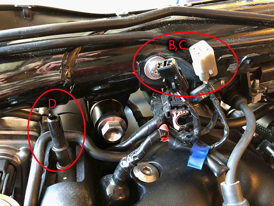
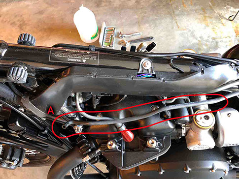
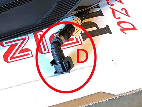
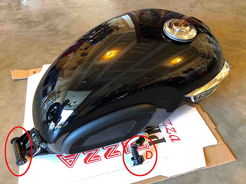
I won’t go into a lot of step-by-step detail here as there are plenty of resources (YouTube, etc.) to show you how to remove the gas tank. Additionally, the T120 service manual instructs you to initially disconnect the battery (ground first). Probably a good suggestion when working with a part of the bike that contains fuel and electrical connections. My gas tank was full, so I did siphon all the gas (or as much as possible) from the tank. Also, make sure the key is removed from the ignition during all these steps. Basically, you remove the seat; then undo and remove the bolt at the back of the tank (See Step 1E for bolt location). Lift the back of tank up approx. 3-6” to allow access under the tank. Pull breather hose away from (2) clips located on the underside of the fuel tank on the bottom edge (LH side), then pull the breather hose completely off of the bottom of the tank (LH side near front) - (Pic Highlight A). Undo the electrical connections for the fuel pump and fuel level sensor under the tank (RH side) – (Pic Highlight B and C). Undo and pull up the fuel hose (RH side) from the fuel rail – To do this, pull back on the locking tab, push buttons on each side (inner and outer) and at the same time wiggle the connector up (Pic Highlight D). Some fuel will leak out of the hose, although the tank will not empty onto the floor as the opening at the bottom of the tank is “self-sealing”. Lifting the tank up at the back (near area where the fixing bolt was removed), hold tank (completely so that you can safely carry it once removed) and slowly and carefully pull backwards to remove tank. Set the tank on a piece of cardboard on the floor or workbench.

<click to enlarge>

<click to enlarge>
STEP 2
REMOVE THE HEADLIGHT
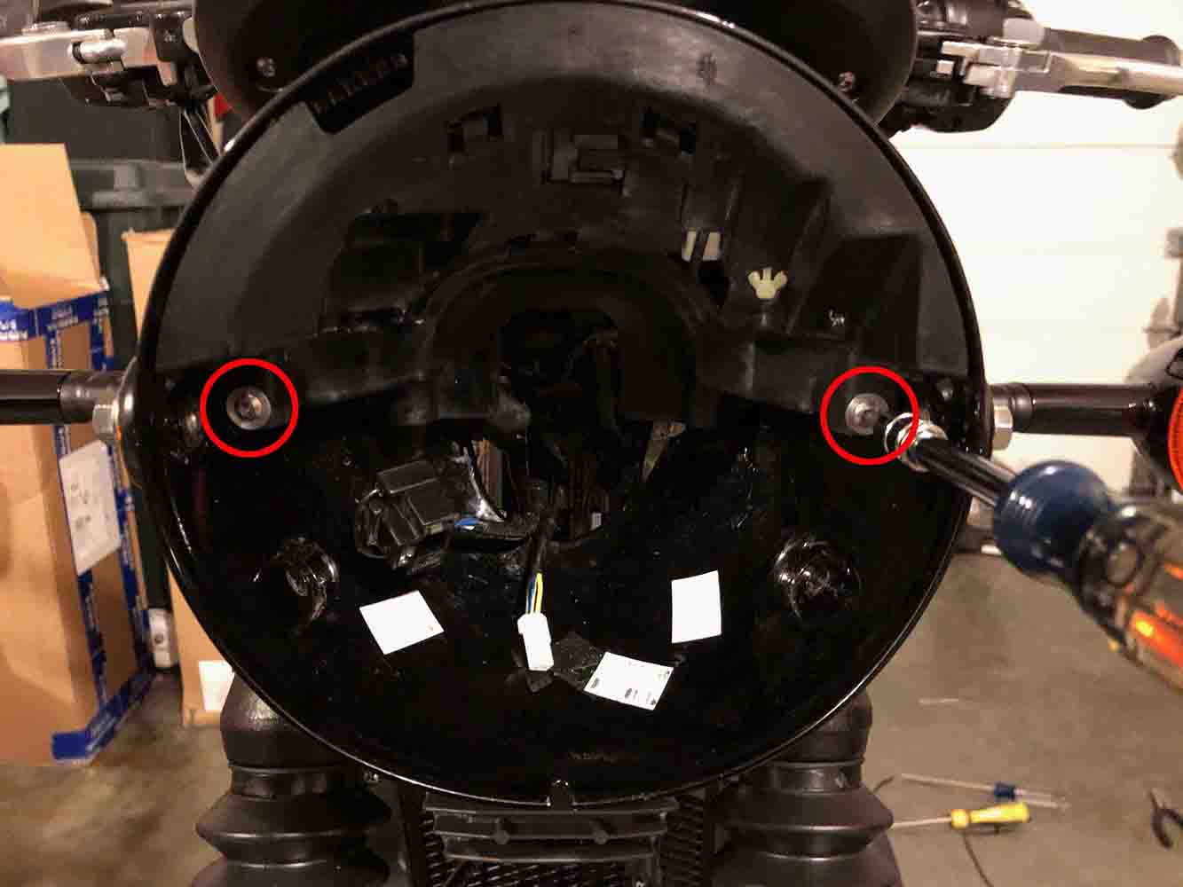
Again, I won’t go into a lot of step-by-step detail here as there are plenty of resources (YouTube, etc.) to show you how to remove the headlight. Basically, you remove the two screws on each side of the headlight bucket and rotate the headlight up (to release hook at the top) and swing forward to free the headlight from the bucket. Remove the large headlight plug and then CAREFULLY, remove the small connector at the back of the headlight. I was not so careful and ended up breaking the latch on this plug which I ended up replacing (not fun!). Remove the headlight and side aside.
STEP 3
REMOVE CONNECTORS FROM HEADLIGHT BUCKET
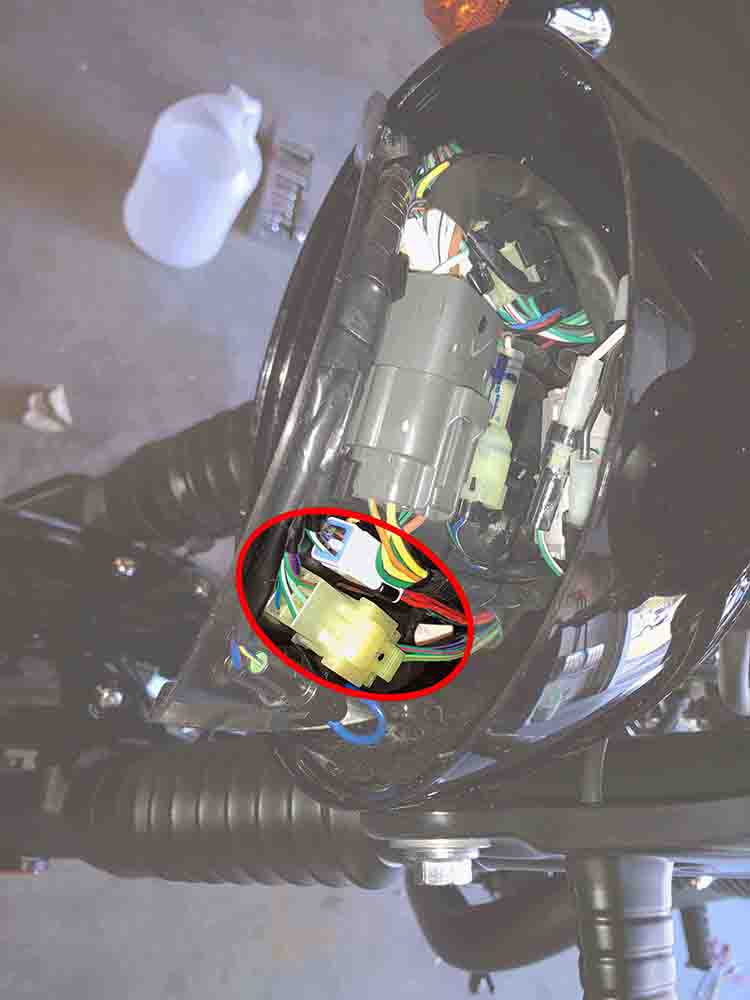
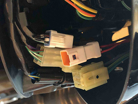
Remove the two screws that hold the plastic cover (inside the headlight bucket), and gently pull the cover forward to expose the plugs/wiring. The (2) turn signal connectors we will be working with are located on the LH side of the bike (inside the headlight bucket) as shown.

<click to enlarge>
STEP 4
REMOVE CONNECTORS FROM HEADLIGHT BUCKET
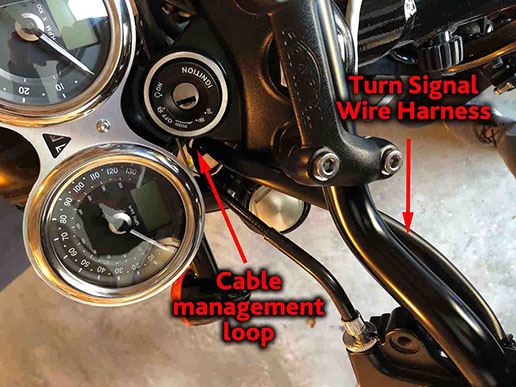
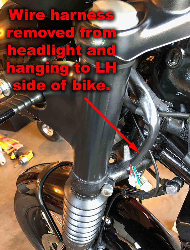
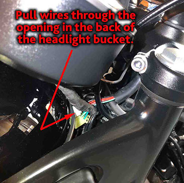
Locate the (2) turn signal connectors inside the headlight bucket (coming from the turn signal switch) as shown in the first picture (and highlighted in the previous step). Disconnect these (2) connectors. Note how the turn signal wire harness is routed from the LH grip so that you can reassemble using the same path (Take before pictures with your smartphone/camera before disassembling) . Carefully pull the turn signal wire harness through the opening in the back of the headlight bucket and allow it to hang from the LH grip on the LH side of the bike (as shown).

<click to enlarge>

<click to enlarge>

<click to enlarge>
STEP 5
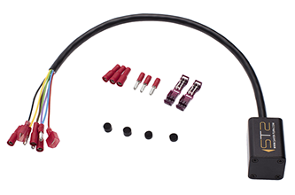
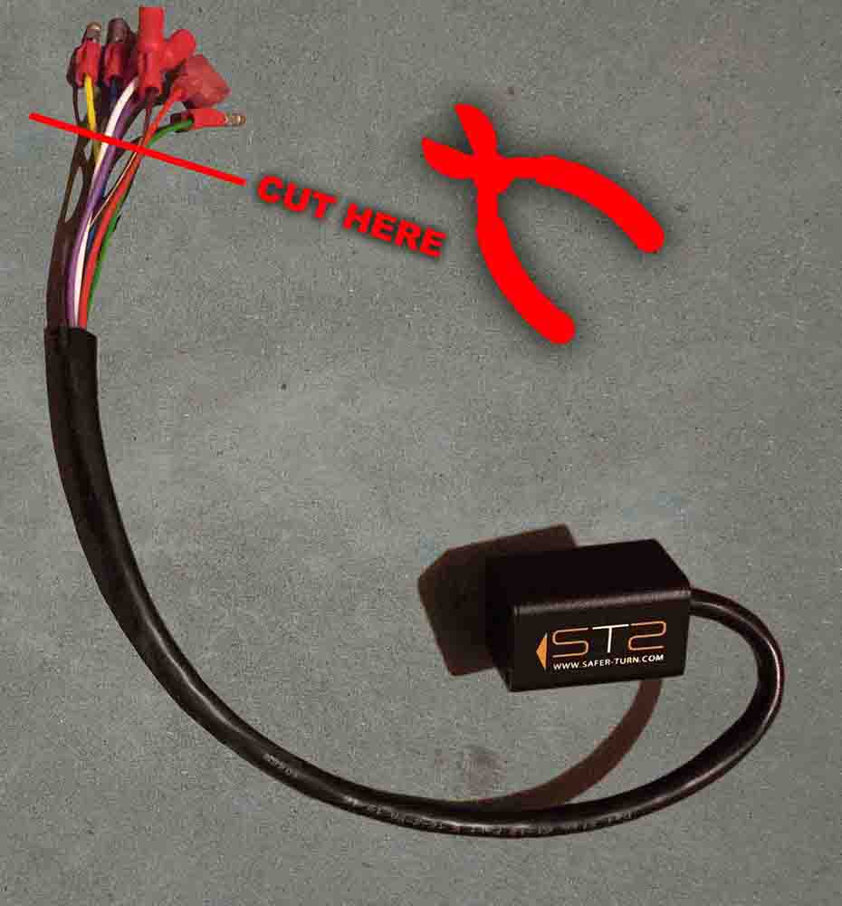
CUT CONNECTORS OFF STS WIRES
Cut all the connectors of the wires on the STS unit. These ends will be connected to the end of the 36” extension cable using solder or (in my case) solderless connectors to save space under the tank.
STEP 6
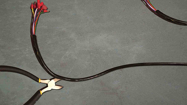
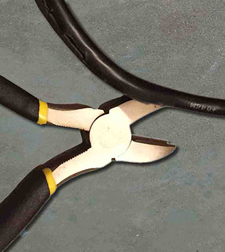
REMOVE OUTER SHEATH FROM 36” EXTENSION
Completely remove the black outer sheath from the entire length of the 36” extension cable (obtained from STS or reseller like A&J Cycle): Starting at the end of the black outer sheath where the wires exit - Use a sharp wire cutter and carefully run the jaw of the cutter along the inside of the black outer sheath, so that the sharp cutting jaw is facing out and the smooth rounded side of the cutter slides harmlessly along the wires inside. Go slowly and be very careful – If any wires are nicked you will need to replace this extension cable. The black outer sheath on mine was quite thick. Push away from yourself and take your time. You can also pull on the jacket to tear it open once you get a cut started. This will step is required to reduce the diameter of this cable and also allow you to eliminate the RED and BLACK wires from inside this extension cable in a later step. (Note: These RED and BLACK wires are no longer needed as the power/ground connections will be made under the seat – However, save these wires for use later to make wire leads.) Eliminating the black outer sheath will also make this extension more flexible which will make it easier to route under the tank and into the headlight assembly.
PAGE