

STS INSTALLATION - 2016 Triumph T120
PAGE
STEP 7
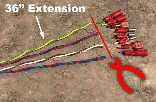
CUT CONNECTORS FROM ONE END
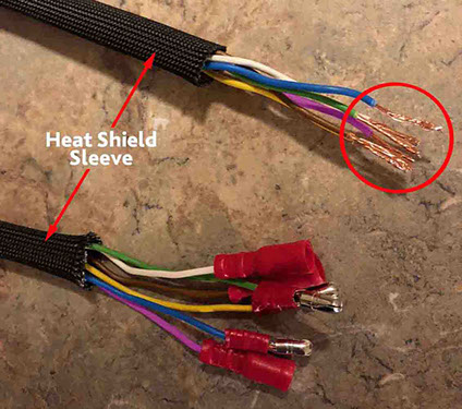
Assuming your 36” extension cable has electrical connectors at both ends (like the one I received directly from STS); cut the connectors from the ONE end of the 36” extension cable that will connect under the seat to the wires on the STS unit (Yellow, Green, Blue = Female Socket, and Purple, Brown, White = Male Bullet as shown in pic below). IMPORTANT – DO NOT CUT THE END WITH THE FOLLOWING CONNECTORS: Yellow, Green, Blue = Male bullet, and Purple, Brown, White = Female socket – Those connectors will be used later to connect to the turn signal wires. Cut as closely to the connectors as possible. This end will be later stripped and connected with the ends of the wires coming out of the STS unit using solder or heat shrink solder-less connectors to save space.
STEP 8
REMOVE RED/BLACK WIRES FROM EXTENSION CABLE
The BLACK and RED wires are no longer needed in the 36” extension cable as these connection will be made under the seat at the rear of the bike. Carefully, remove the RED and BLACK wires from the bundle of wires of the 36” extension. Save both the RED and BLACK wire for later use (to create 12v+ power leads and ground).

STEP 9
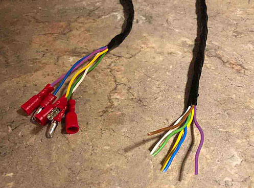
WRAP WIRES IN BLACK ELECTRICAL TAPE
Starting 2-3” from the connectors at one end wrap the wires from the 36” extension cable TIGHTLY with black electrical tape as shown. Stop wrapping tape approx. 2-3” from the end where the connectors have been removed.
STEP 10
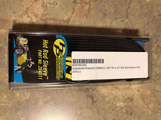
INSERT 36” EXTENSION CABLE INTO HEAT SLEEVE
Cut 3/8” ID black heat shield sleeve (Heatshield Products Hot Rod Sleeve Part #204011 - Click here to buy on Amazon.com), so that there is approx. 2” of wire exposed at each end of the 36” extension cable. Insert the 36” extension cable (wrapped in black electrical tape) into the heat shield sleeve. (This heat shield may not be required, but it will protect the wires from the engine heat.) Strip the ends of the wires without connectors approx. 3/8”.
STEP 11
PREPARE TO TAP INTO 12V+ LEAD (USB PORT)
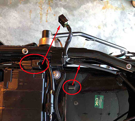
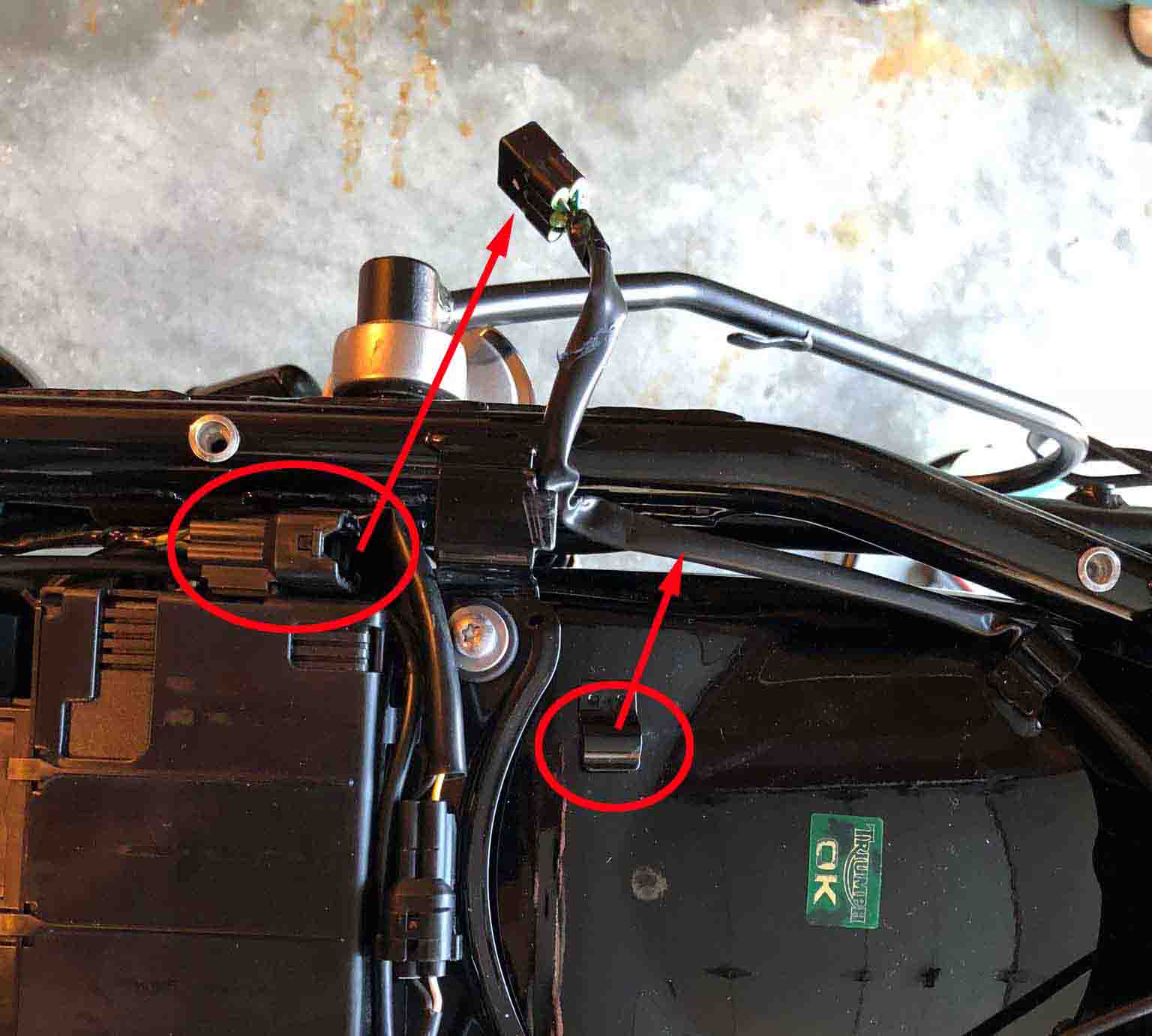
Disassemble the plug on the RH side under the seat as shown. Unclip it from the rear fender and move off to the side out of the way. (This is not entirely necessary, but may help you to better access the wire you will be splicing into.)
<click to enlarge>
STEP 12
CREATE (2) 12V+ WIRE LEADS
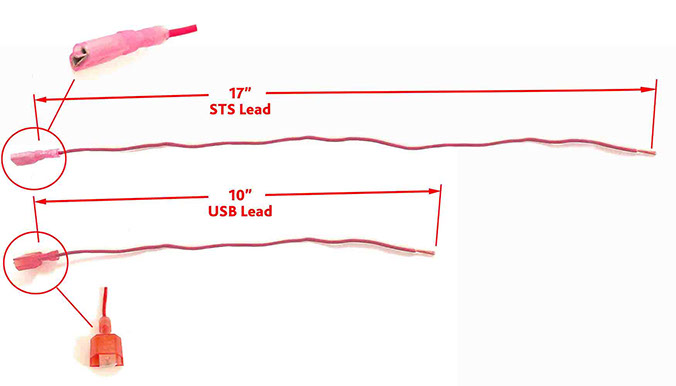
Using the RED wire (removed from the 36” extension cable) from previous Step 8, cut (2) pieces: One to the length of 17” and one to a length of 10”. Strip both ends of each wire approx. 1/4". Crimp on a 22ga male spade connector (as shown) to the end of the 10” USB Lead. Crimp on a 22ga female spade connector socket (as shown) to the end of the 17” STS Lead. (I used the Titan Tools 11477 Terminal Crimper - Click here to buy on Amazon.com). These connectors will be connected together later to feed power to the STS unit.
PAGE