

STS INSTALLATION - 2016 Triumph T120
PAGE
STEP 13
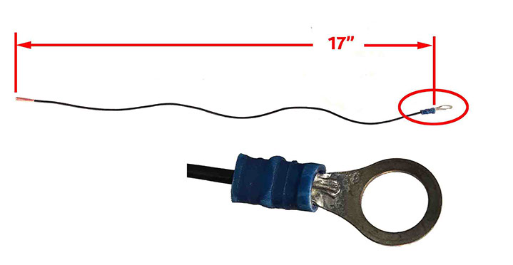
CREATE A GROUND WIRE CONNECTION
Using the BLACK wire (removed from the 36” extension cable) from previous Step 8, cut to a length of 17”. Strip one end of the wire approx. 1/4". Purchase a 22ga wire ring terminal (for a 5/16” stud). Crimp the connector onto the black wire. (Note: I couldn’t find 22ga 5/16” ring connectors so I pulled back the blue plastic sleeve on the connector intended for a larger gauge wire and soldered the black wire to the connector – I then pulled up the plastic sleeve and crimped after soldering.) IMPORTANT: Do not connect this BLACK wire to the battery terminal ground at this time!
STEP 14
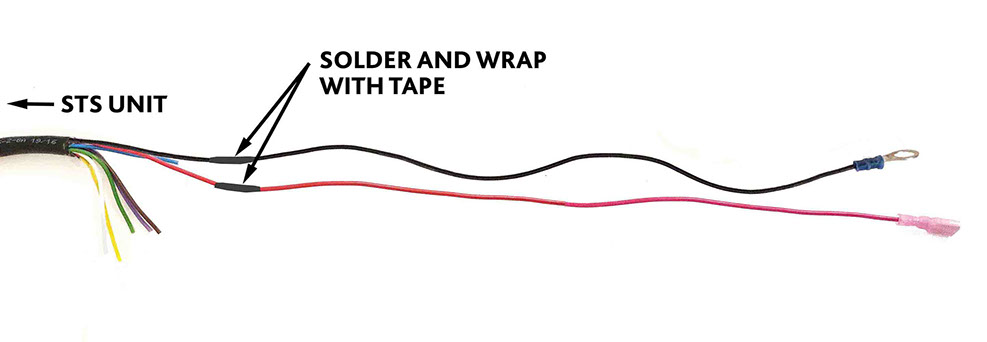
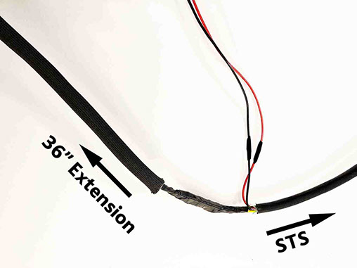
SOLDER 17” GROUND AND 12V+ LEADS TO STS UNIT
Solder the 17” BLACK Ground (with ring terminal created in Step 13) to the black lead coming off of the STS unit – Wrap with black electrical tape. Solder the 17” RED 12V+ lead (created in Step 12) to the red lead coming off of the STS unit – Wrap with black electrical tape (or shrink tubing). (Note: If not comfortable with soldering you could use 22ga bullet connectors or Wirefy solderless connections – See later steps for details.)
STEP 15
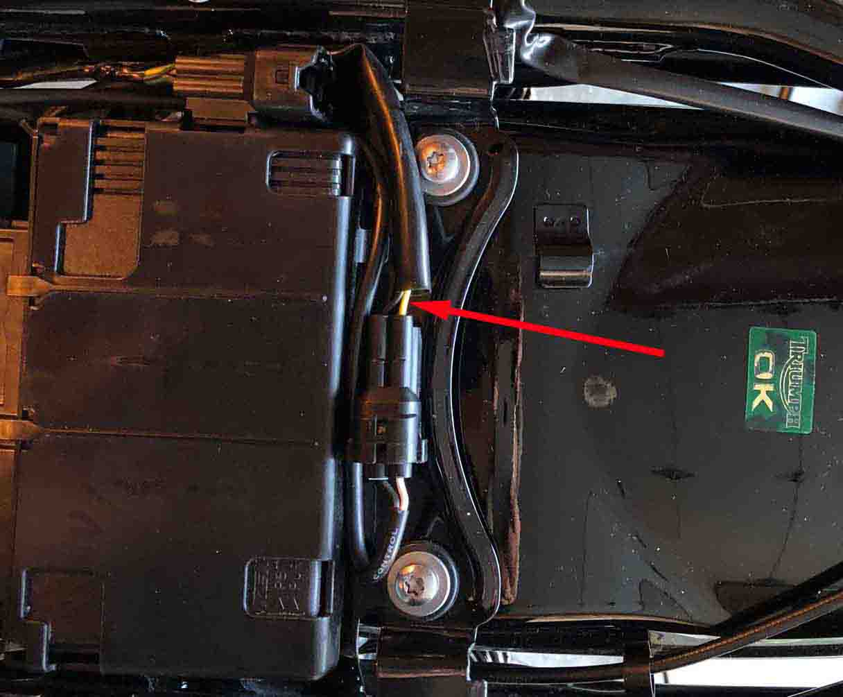
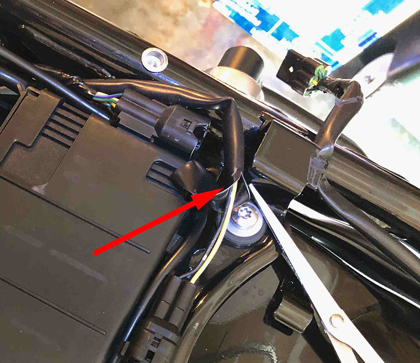
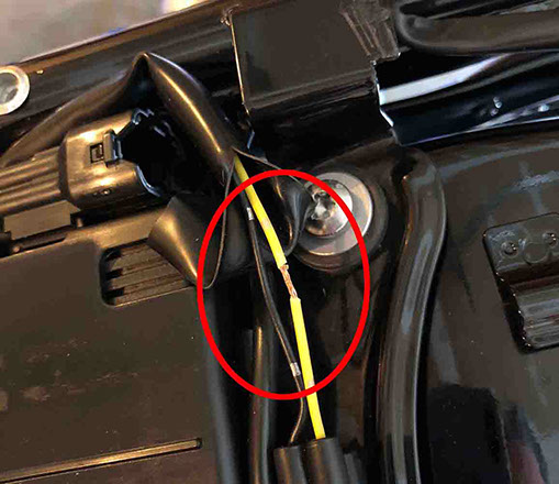
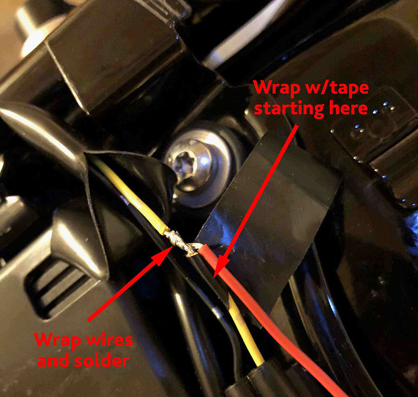
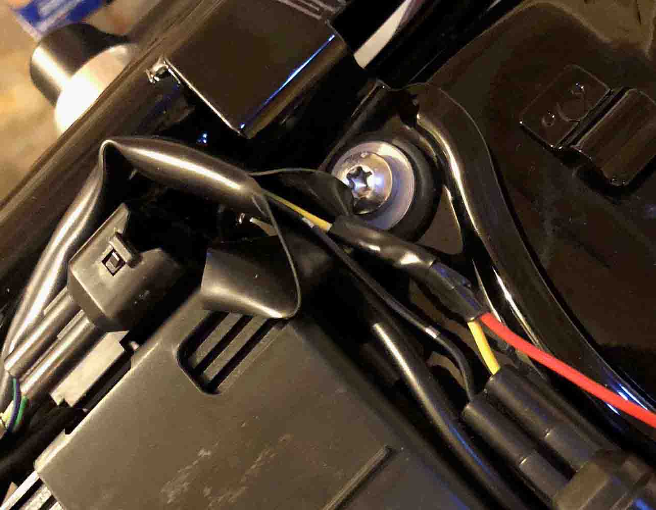
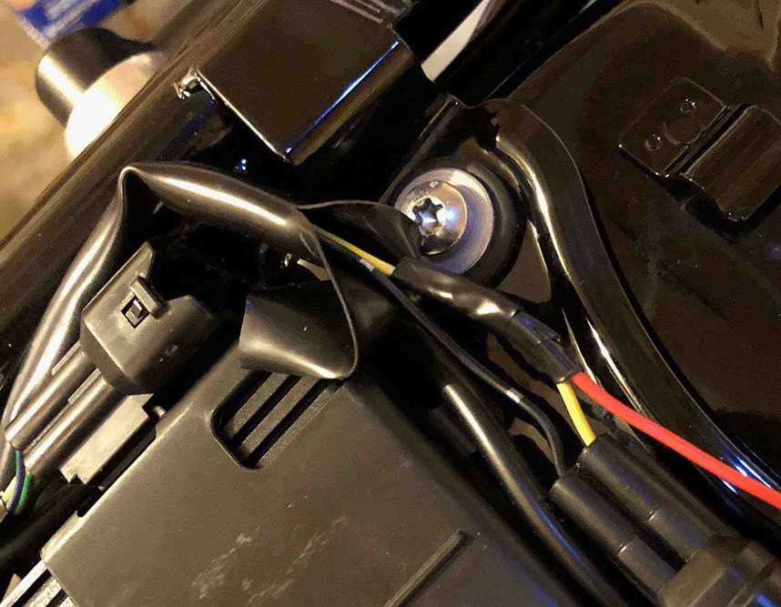
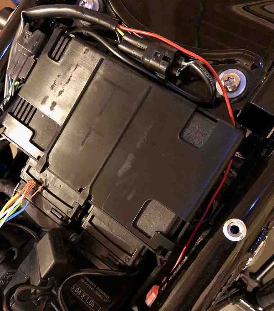
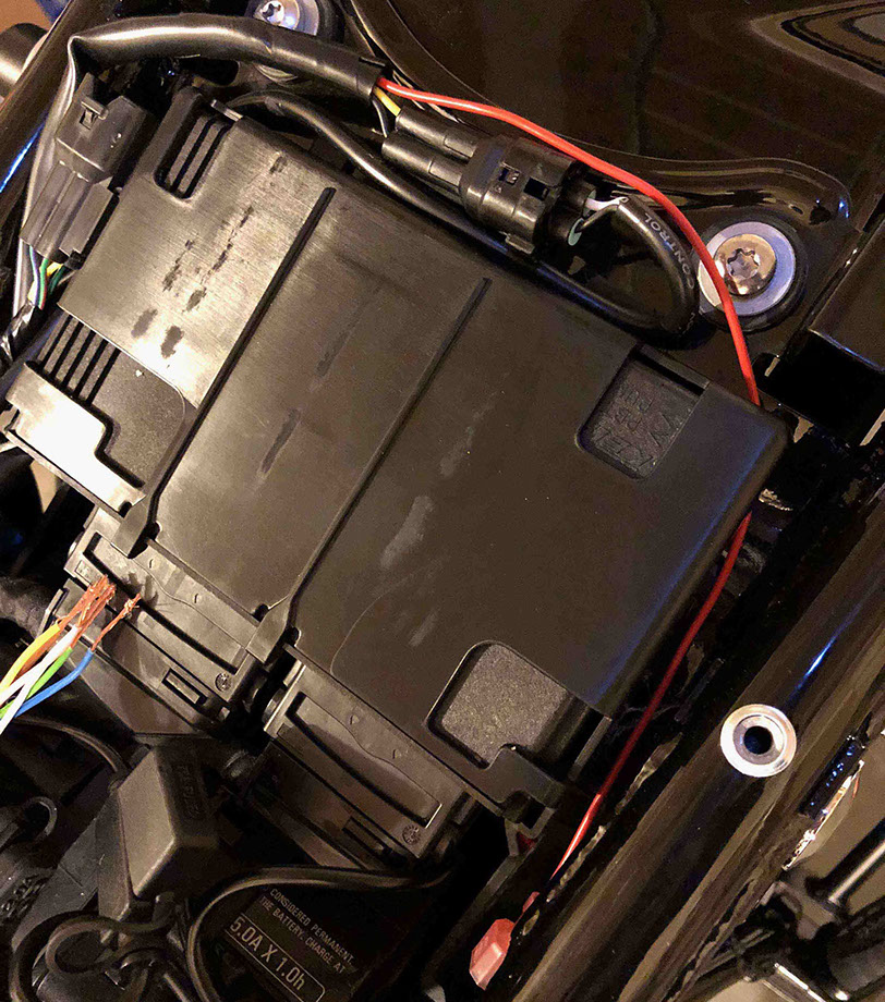
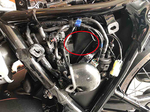
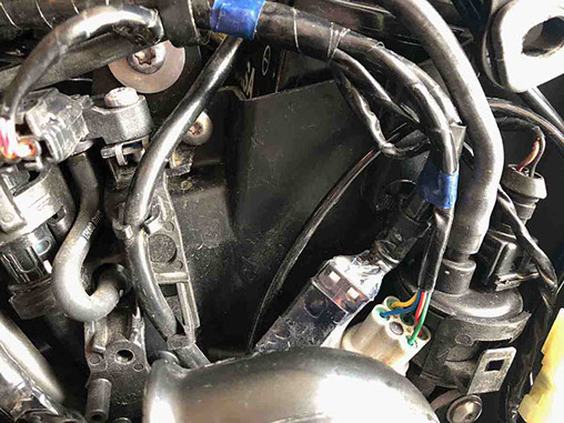
TAP INTO 12V+ WIRE LEAD (USB PORT)
Locate the YELLOW wire going to the USB port under the seat of the T120. Carefully cut a 2” slit in the black plastic cover (with scissors) to expose the YELLOW (AND BLACK) wire. Carefully, strip away approx. ¼” of wire housing from the yellow wire approx. 2” from the connector (as shown) – DO NOT CUT THE YELLOW WIRE, and be careful not to nick the wires when stripping away the wire housing. Wrap the stripped end of the 10” RED USB wire lead you created in Step 12 around the exposed wire on the YELLOW 12V+ lead. Place a piece of cardboard under the area you will be soldering and solder the stripped end of the RED wire to the exposed wire on the YELLOW 12V+ lead. Let solder cool and tape this connection (with electrical tape). Pull outer plastic cover back over the wire and wrap the plastic cover with electrical tape. Route the red wire lead as shown. IMPORTANT: Do not connect the RED wire coming from the YELLOW 12V+ power lead to the RED wire on STS unit at this time! (Note: If not comfortable with soldering you could use the wire tap connector provided by STS.)

<click to enlarge>

<click to enlarge>
<click to enlarge>


<click to enlarge>
<click to enlarge>
<click to enlarge>
STEP 16
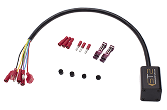
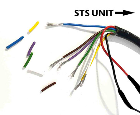
STRIP REMAINING WIRES ON STS UNIT
Strip the ends (1/4” – 3/8”) off the remaining wires on the STS unit.
STEP 17
CONNECT EXTENSION CABLE TO WIRES ON STS UNIT
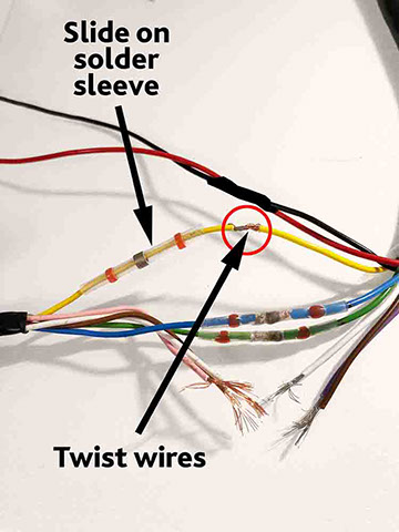
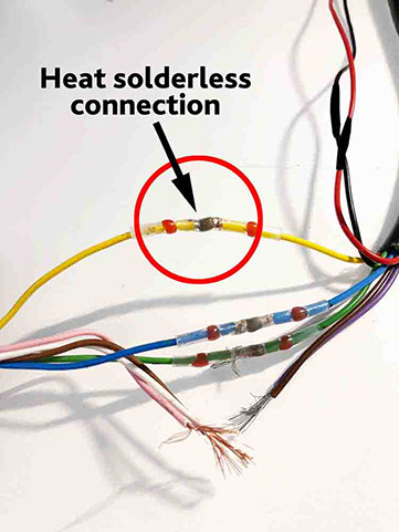
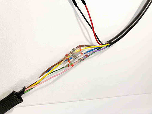
(Note: This wires in this step could ideally be individually soldered and wrapped with tape or heat shrink tubing, however, I wanted to try my Wirefy solderless shrink connectors.) I purchased the Wirefy solderless shrink connectors from Amazon.com to complete this step. The Wirefy connectors are easy to use and also incorporate a shrink housing to seal the connection. (Note: I suggest not to use bullet connectors for this connection as this part of the cable will need to fit under the tank and space is limited.) Slide the appropriate shrink connector onto one of the wires. Then twist the matching (color) wires together and pull the shrink connector over the connection so that the solder is centered on the twisted wires. Heat (with small torch lighter or heat gun) as directed until the solder connection is complete and the shrink housing seals around the wires. (Note: I practiced on a few scraps of wire first to practice – It’s easy to use too much heat!) Wrap the bundle completely with black electrical tape to complete the extension cable assembly.
STEP 18
LOCATE WHERE THE STS WILL BE MOUNTED
Remove the LH Side Cover (pulls off with some force). The STS unit will be finally mounted under the LH Side Cover as shown. (Note: You might have to gently move some wires in this area to the side to make room in this area.)
PAGE