

STS INSTALLATION - 2016 Triumph T120
PAGE
STEP 19
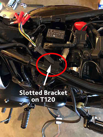
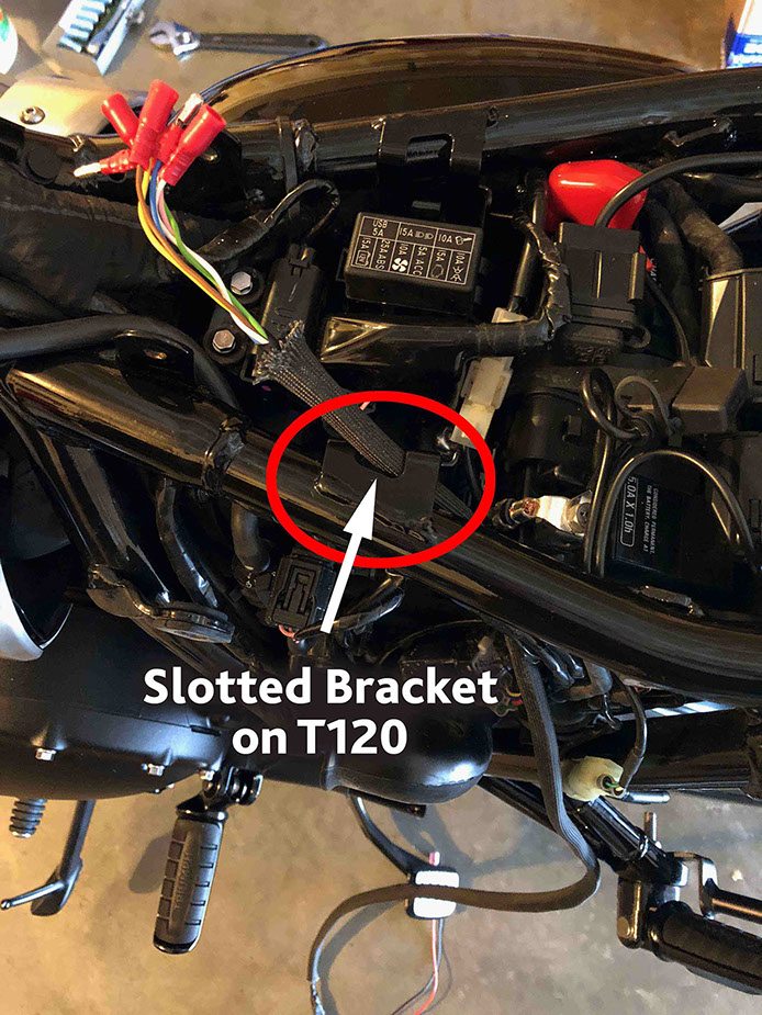
ASSEMBLE STS HARNESS ASSEMBLY ONTO THE BIKE
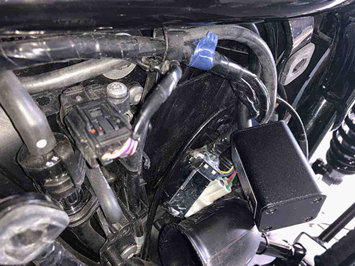
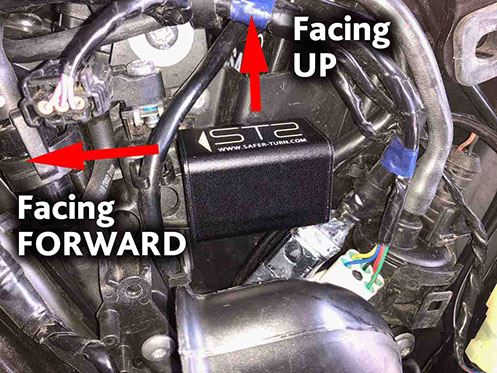
Route the wire assembly up through the space on the LH side of the bike (under the side cover) where the STS unit will be mounted. Pass wires up through the slotted bracket (under the seat) as shown. (Note: This slot will help manage the cables and keep them securely located in position.) Continue to pull the wires up through this slot (including the BLACK ground and the RED 12v+ power lead) until the STS unit is located in the area under the side cover as shown. Gently form the wire bundle on the STS unit into a large “C” shape so that the arrow on the STS unit can be facing forward with the STS logo facing UP and the STS unit is sitting basically level. The wire housing exits the back of the STS unit and curls up to the slotted bracket behind the existing T120 wiring. (Note: We will “permanently” mount the STS unit here later using cable ties and/or heat resistant double-sided tape.)
<click to enlarge>

<click to enlarge>
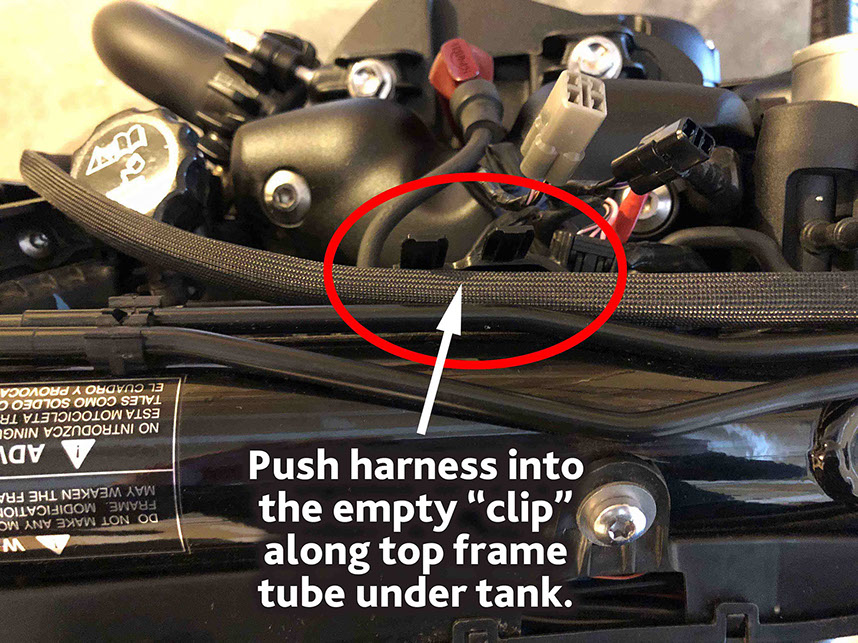
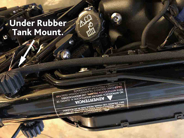
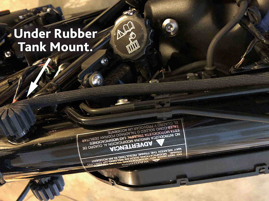
STEP 20
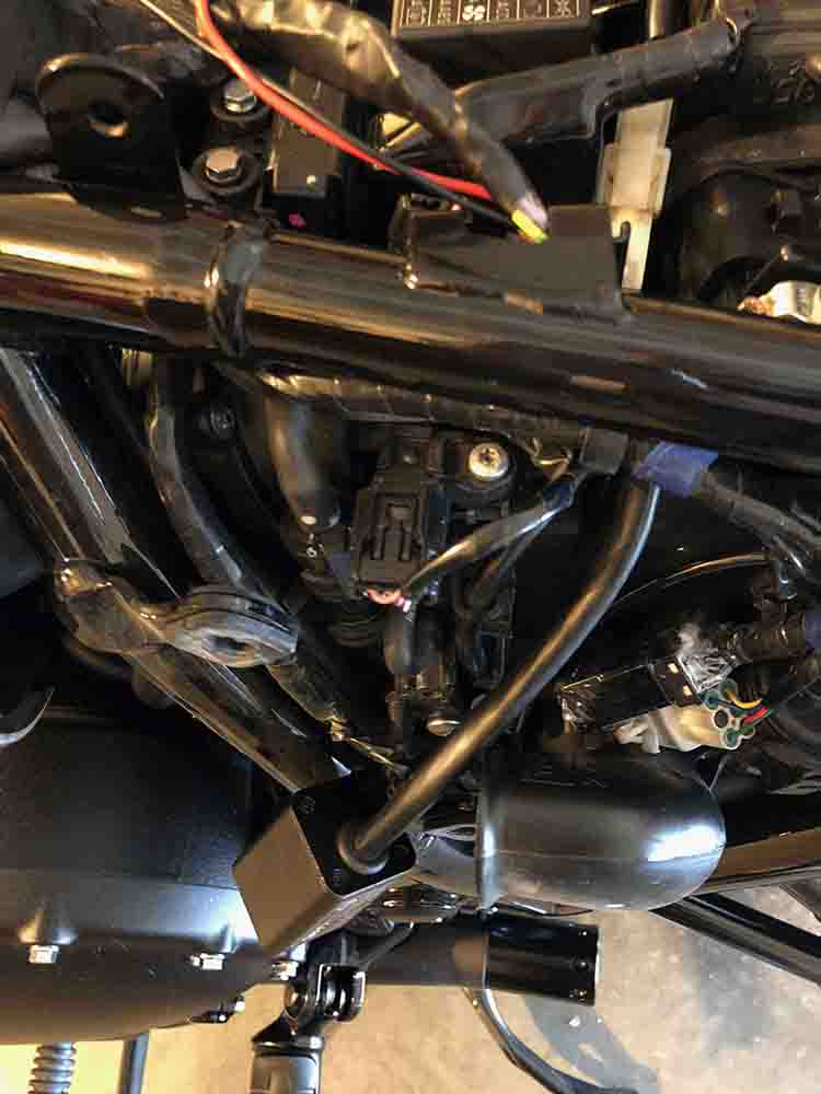
ROUTE STS HARNESS ASSEMBLY UNDER THE TANK
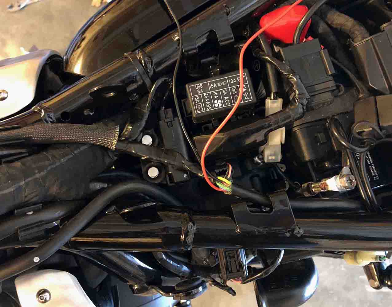
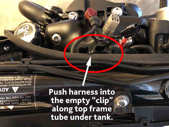
Clip the heat shielded wire bundle in the empty bracket under the back of the tank (near the electrical connectors) as shown. Then to route the heat shielded wire bundle up along the frame. Finally, route the heat shielded wire bundle up under the RH side rubber front tank mount and around the front of the head tube back to the LH side of the bike where the turn signal wire harness is hanging (see Step 4).
<click to enlarge>

<click to enlarge>
<click to enlarge>
<click to enlarge>

POINT OF NO RETURN!!!
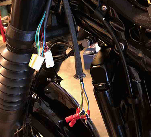
STEP 21
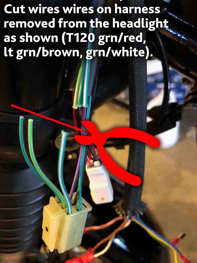
CUT WIRES AT TURN SIGNAL CONNECTOR
Locate the larger turn signal connector (removed from the headlight in a previous step and now hanging down the LH side of the bike). ONLY cut the (3) wires as shown (2016 Triumph T120: grn/red, lt grn/brown, grn/white) approx. 2-3” from the connector. DO NOT CUT THE OTHER 3 WIRES GOING TO THIS CONNECTOR! Note: To make it easier to access these wires you might need to cut the outer plastic wire harness sleeve 2”-3” and pull it back.
STEP 22
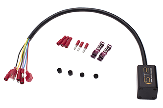
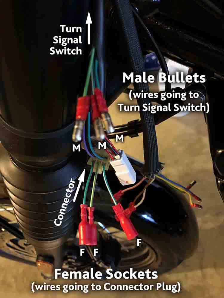
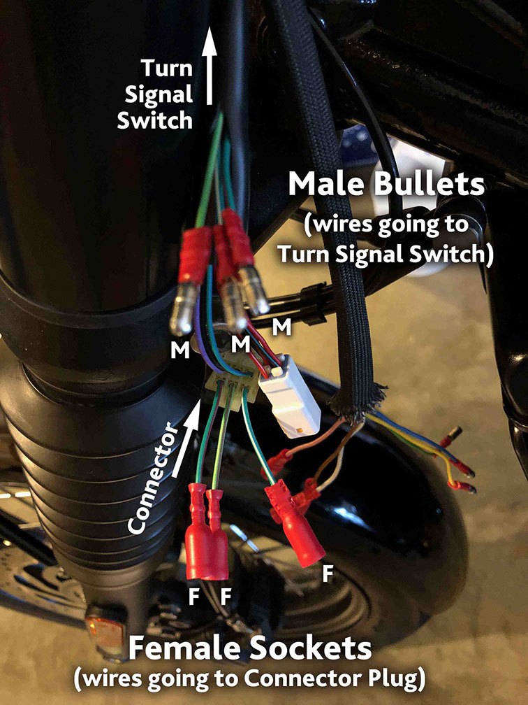
CRIMP ON CONNECTORS
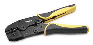
Strip the ends of the (3) wires going to the Turn Signal Switch approx. ¼” and crimp on the 22ga Male Bullet connectors. Strip the ends of the (3) wires going to the Connector Plug approx. ¼” and crimp on the 22ga Female Socket connectors. See photo below for details. Take your time and make sure you have solid crimped connections.
<click to enlarge>
STEP 23
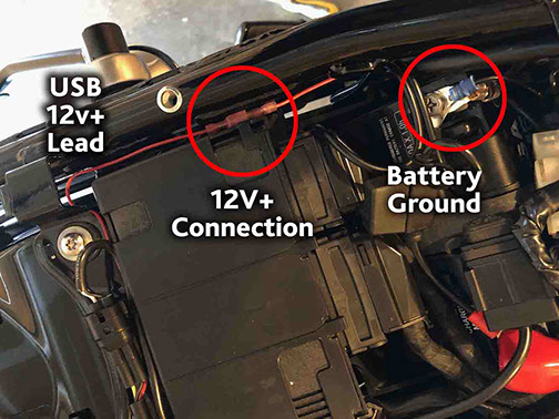
CONNECT 12V+ POWER SUPPLY AND GROUND
Route the 17” BLACK ground wire from the STS harness assembly back to the battery ground. Unscrew the battery ground from the battery. Slip the ground ring over the battery ground screw. Tighten the battery ground screw to secure the ground wire. (IMPORTANT! Check to make sure your key is removed from the ignition before continuing to connect the 12V+ power leads.) Route the 17” RED 12V+ power lead coming from the STS harness assembly back to the 12V+ power lead coming from the (yellow) USB wire tap. Plug the female connector coming from the STS harness into the male connector coming from the USB 12V+ wire tap. Tuck the 12V+ and ground wires down into the area under the seat so that they do not get pinched when the seat is re-attached.
<click to enlarge>

PAGE