

STS INSTALLATION - 2016 Triumph T120
PAGE
STEP 24
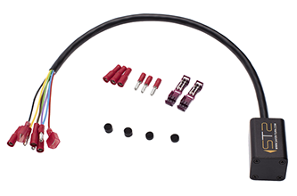
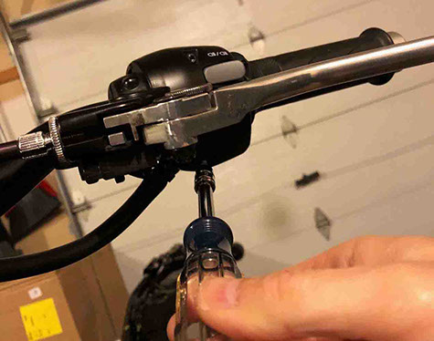
CONNECT STS HARNESS TO CONNECTOR PLUG
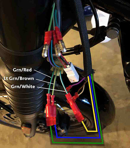
Plug the male bullet connectors coming from the end of STS wiring harness assembly into the female sockets on the wire leads coming from the Turn Signal Connector as follows:
• STS Green (male bullet) into TURN SIGNAL Connector Grn/Red (female socket)
• STS Blue (male bullet) into TURN SIGNAL Connector Lt. Grn/Brown (female socket)
• STS Yellow (male bullet) into TURN SIGNAL Connector Grn/White (female socket)
IMPORTANT! Do not connect white, brown and purple STS wires at this time! These three wires will be connected in a later step AFTER performing the initial STS system test in the next step.
<click to enlarge>

STEP 25
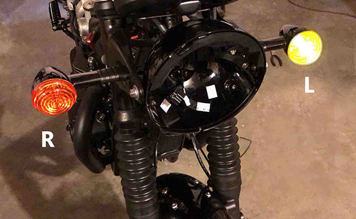
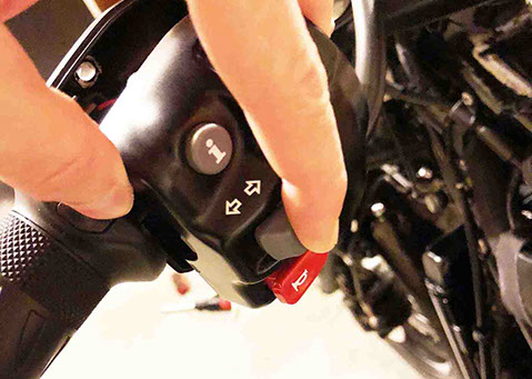
INITIAL STS SYSTEM TEST
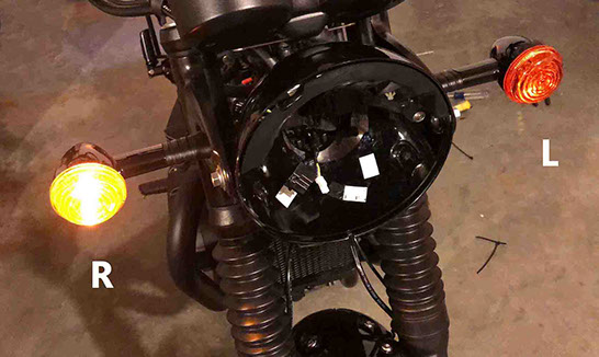
Looking at the bike from the front - Insert the key into the ignition and turn the ignition ON. The turn signals should flash for 1 second as follows: LEFT (LH side) turn signal first, then the RIGHT (RH side) turn signal as shown below. When the correct test pattern is observed turn the ignition off and remove the key. IMPORTANT! Do not proceed with installation process until the turn signals flash in the proper LEFT/RIGHT sequence.
Note: If turn signals do not flash, turn the key off and check to make sure there is power to the STS unit (and it is properly grounded). If the lights flash in the opposite order, then most likely one of the connections (from Step 24) is reversed.
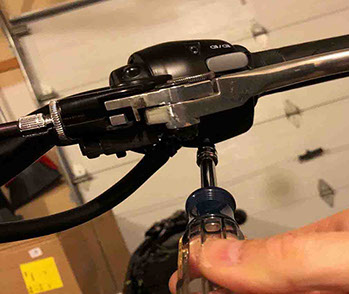
STEP 26
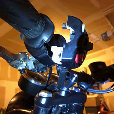
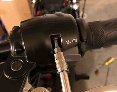
DISASSEMBLE THE LH GRIP
Remove the (2) torx screws that hold the LH Turn Signal housings together (as shown).

STEP 27
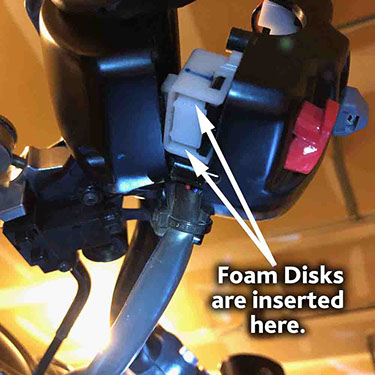
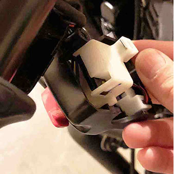
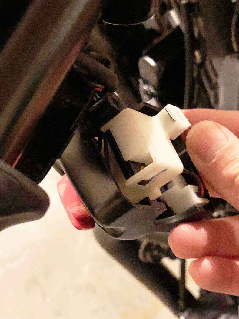
DISASSEMBLE THE LH GRIP
Open the housings. The foam disks are inserted into the turn signal switch from the bottom (see pic below).
<click to enlarge>

STEP 28
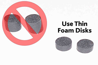
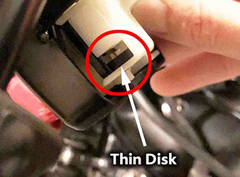
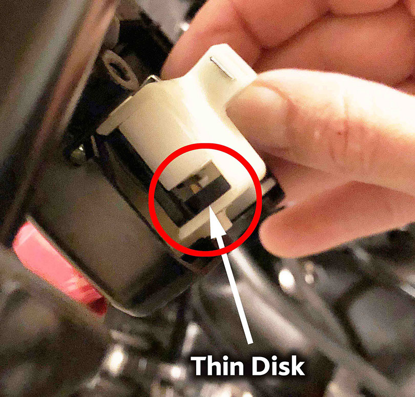
INSERT FOAM DISKS
Push the turn signal switch to one side to lock open a wider gap on one side of the switch to make it easier to insert the first foam disk. Insert (1) thin foam disk (Triumph T120) from below into the widest opening (as shown).
<click to enlarge>
<click to enlarge>
STEP 29
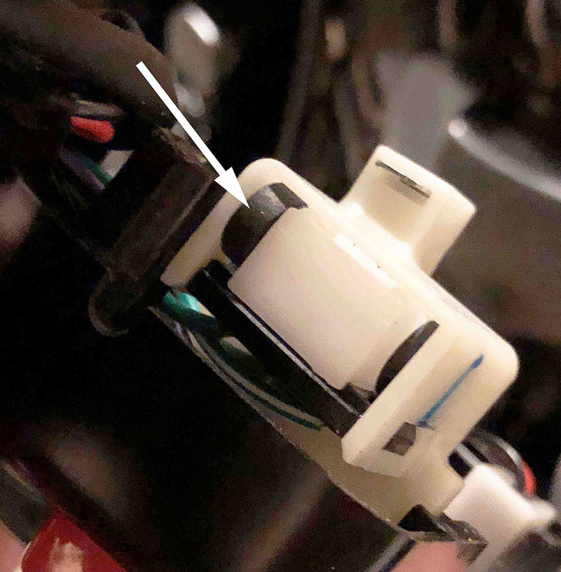
INSERT FOAM DISKS
Push the turn signal switch to the other side to open a gap to make it easier to insert the second foam disk in the other side. Note: this gap won’t be as large as the first gap due to the compressed foam disk inserted from Step 28. Insert (1) thin foam disk into the opening (as shown).

<click to enlarge>
STEP 30
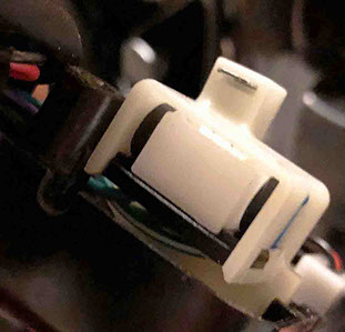
INSERT FOAM DISKS
Check to make sure both disks are completely inserted into the switch housing (not sticking out past the plastic switch housing) – Then reassemble the housings and secure the (2) torx screws.
<click to enlarge>

PAGE