

STS INSTALLATION - 2016 Triumph T120
PAGE
STEP 31
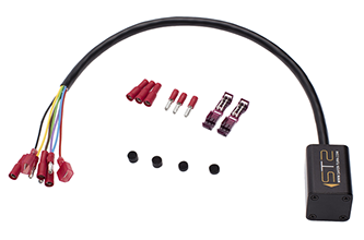
CONNECT STS WIRING HARNESS TO TURN SIGNAL
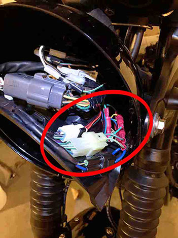
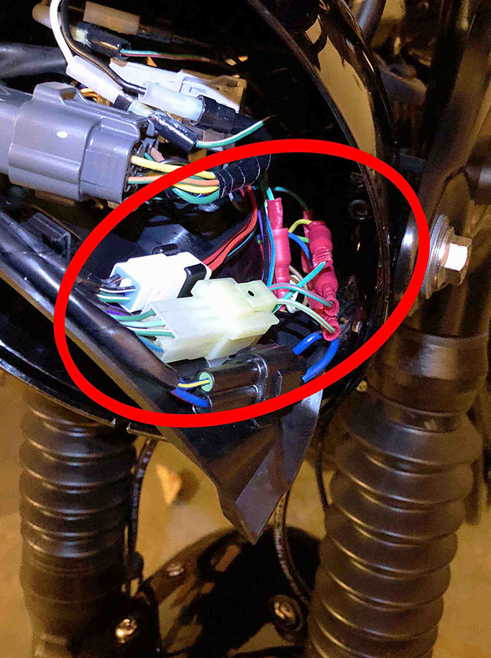
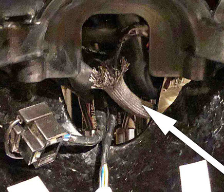
Re-route the turn signal wire harness and STS harness assembly into the opening in the back of the headlight bucket. Make sure to follow the same path for the turn signal harness before it was removed (Step 4). Perform an initial wire harness path check by turning the handlebars right and then left to make sure the original turn signal harness and the STS harness assembly do not get pinched – Adjust or re-route as needed. Connect the original turn signal connector plugs back into the connectors inside the headlight bucket (unplugged in Step 4). Plug the female sockets on the STS wiring harness assembly into the male bullet connectors coming from the Turn Signal as follows.
• STS Purple (female socket) into TURN SIGNAL Grn/Red (male bullet)
• STS Brown (female socket) into TURN SIGNAL Lt. Grn/Brown (male bullet)
• STS White (female socket) into TURN SIGNAL Grn/White (male bullet)
Finally, check to make sure the turn signal connector plugs are secured in the original position using the original hold-down clips where necessary.
<click to enlarge>
STEP 32
TURN SIGNAL CHECK
IMPORTANT! Check to make sure your turn signals work before continuing. Insert the key and turn the ignition on. Check to make sure the initial flashing LEFT/RIGHT sequence happens. Note: I think this will happen every time you start your motorcycle to let you know that the STS unit is functioning. Then press your turn signal switch to the left and right and check to make sure it works in both directions before continuing. To manually turn off your turn signal press it again in the same direction you used to turn on the turn signal – Your center push-button turn signal release is no longer functioning because of the foam disks that were inserted (Steps 28 & 29). Note: Checking the turn signals when the bike stationary means the STS unit will not turn them off – The bike must be ridden for the STS system to be able to turn off the turn signals.
Note: The foam disk might make it difficult to press the turn signal button and may require more force than normal. This should get better over time, but if it is too difficult to press, then the force can be reduced by carefully removing the foam disks and using a leather punch tool to cut a small hole in the middle of the foam disk. If you live in a cold climate and are performing this modification over Winter, you should wait until it gets warmer before modifying your foam disks. Cold weather will make the foam more difficult to compress and may increase the force required to activate the turn signals.
STEP 33
RE-ASSEMBLE HEADLIGHT
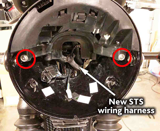
Carefully find room for all the new STS harness bullet connections inside the headlight – Gently position the plastic plate (inside the headlight bucket) into position – If the plastic plate cannot be positioned without force adjust the location of the wires and check to make sure all the plugs are secured in their original location. Take your time and do not force this plastic plate into position. Once everything is positioned correctly, secure the plastic cover with two screws.
Re-check the wire harness path by turning the handlebars right and then left to make sure the original turn signal harness and the STS harness still do not get pinched – If necessary, remove the screws that hold the plastic plate and re-adjust or re-route the wiring harnesses as needed.
STEP 34
RE-ASSEMBLE HEADLIGHT
Place the headlight assembly into the headlight bucket - Connect the (2) headlight plugs, hook the light at the top, and rock your headlight back into it’s original position. Secure with (2) screws on the sides of the headlight bucket.
STEP 35
RE-ASSEMBLE GAS TANK
Check to make sure the STS harness is in the correct position (see previous Step 20). Carefully re-assemble the gas tank – Check the STS harness to make sure it is not pinching or binding anywhere under the gas tank. Reconnect the gas tank fuel connection, electrical connections, and vent tube. Fasten the gas tank into position using the rear bolt. Note: If gas was siphoned from the tank, don’t forget to refill the tank before going for a ride - Doh!
STEP 36
SECURE THE STS UNIT
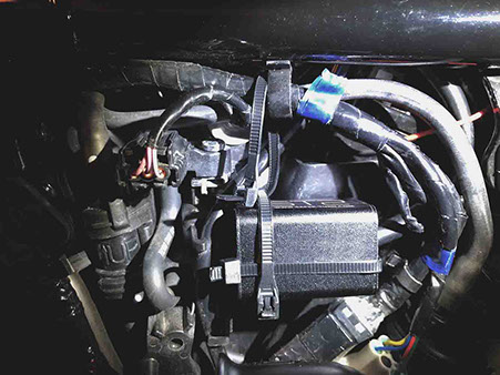
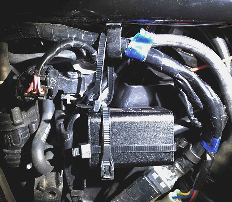
Using (heavy duty) zip ties – Secure the STS unit to the bike under the LH Side Cover. I used (3) and even made use of a hole in the plastic housing on the bike at the front of the STS unit to help secure it. In addition to the zip-ties, you can also use automotive double-side adhesive tape (Click here to purchase from Amazon.com) and place a small square of tape on the back between the STS unit and the bike, but I would not rely on tape by itself (without zip-ties) to hold the STS unit securely in place.
<click to enlarge>

STEP 37
RE-ATTACH THE LH SIDE COVER
Re-attach the LH side Cover.
STEP 38
RE-ATTACH THE SEAT
Double check that all of the new wiring and wiring harness is in place below the seat and cannot get pinched once the seat is installed – Re-attach the seat.

PAGE
If you like what I do you can make a small $5 donation (or more if you're feeling generous) to my Paypal account. VERY MUCH
appreciated by yours truly!